by David A. Ennis
Winnipeg, Manitoba
|
This is the second of two articles on the history of the Greater Winnipeg Water District and Shoal Lake as its water source. Editors
The City of Winnipeg, along with the City of St. Boniface and five surrounding municipalities, formed an inter-municipal corporation known as the Greater Winnipeg Water District (GWWD). It was authorized by an Act of the Manitoba Legislature in the first half of 1913. By the end of that year, the partners had made the decision to spend $13,500,000 (probably equivalent to $450,000,000 to today’s voter) to build an aqueduct from Shoal Lake near the Manitoba-Ontario border, some 150 kilometres away, to Winnipeg. The project was completed by the end of 1918, and despite Shoal Lake being 90 meters higher than Winnipeg, implementing the decision was “not all down hill from there.” The terrain between Shoal Lake and the prairie country 25 kilometres east of Winnipeg was treed, crossed by rivers, and included some 80 kilometres of muskeg or swamp. For the most part, the region was uninhabited and difficult to access. The engineers, administrators, and contractors executed a unique project that is remarkable for its scope and its lasting ability to serve the needs of the City of Winnipeg. In so doing they were confronted with and overcame unique physical and environmental conditions using creative design, testing, and construction processes.
The elements of the Winnipeg Aqueduct, following the direction of water flow, were as follows: a soft-water source at Shoal Lake that required no treatment for potability, colour, or hardness; a 2.4-kilometre dike across a portion of Indian Bay and a 840-metre channel excavated between Indian Bay and Snowshoe Bay to divert the water of the Falcon River; an intake structure on the edge of Indian Bay; a gravity-fed, enclosed, concrete conduit that conveys water, primarily in an unconfined channel but with some portions under pressure, from the inlet to the City of Winnipeg’s McPhillips Street water reservoir over a distance of 155 kilometres; provision for an equalizing and storage reservoir at Deacon approximately 21 km east of the McPhillips reservoir; crossing the height of land that is the western boundary of the Shoal Lake watershed and going under seven rivers, including the Red River in Winnipeg; and a railway along the full length of the project from Winnipeg to Indian Bay that enabled the initial construction, and is now instrumental to the ongoing operation and maintenance of the system.
We are fortunate that many of the records kept and the photographs taken in the process have survived. It was a significant and high-profile project carried out expeditiously. If the project was to be proposed today the environmental assessment and approval process alone, especially given the number of river crossing, would likely take longer than the time it took to design and build the project in the 1910s.
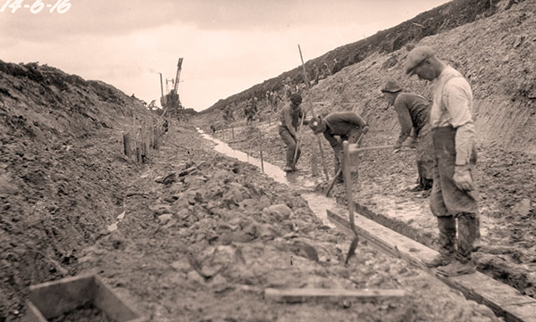
View of a trench bottom before place of the concrete conduit. Although much of the soil volume was excavated by steam-power draglines such as the one seen in the background of this photograph from June 1916, the last few inches had to be removed by hand so the underlying soil was undisturbed.
Source: Winnipeg Water and Waste Department, GWWD #442.
The right-of-way selected was generally 300 feet (91 metres) wide with the railway located 40 feet (12 metres) from the south boundary. At the easterly end, which had more construction challenges such as the depth of excavation, the width was increased to 500 feet (152 metres).
The Act of the Legislature establishing the GWWD saw to it that progress on the project would not be stalled by the acquisition of right-of-way. The enabling section reads:
In no case shall the progress of the works or undertaking of the corporation be hindered, enjoined or delayed in any way, or by any court, on account of any pending arbitration of dispute or disagreement as to damages or value regarding any privilege, water or land entered upon or taken, or proposed to be entered upon or taken, for the purpose of the undertaking authorized by this Act, but the corporation may enter upon, take possession of, hold, use or occupy and enjoy all such land, water and privileges as they are by this Act authorized to do for all the purposes of the undertaking pending any arbitration or settlement of any dispute or disagreement as to damages or value aforesaid, subject to giving up possession of the same in case of default of payment as above provided.
The legislation did not vest the GWWD with the right to dictate terms of land acquisition. It still had the obligation to be reasonable in its offers which could be subject to arbitration. However, it did have the opportunity to occupy an owner’s land without becoming mired in legal proceedings. One wonders whether the project would ever have been built had such delays prevented the start of major construction until after the beginning of the First World War.
The preliminary routing was established by a 1912–1913 survey and investigation by the Winnipeg City Engineer H. N. Ruttan, “to determine the practicality and cost of procuring a water supply for Winnipeg from Shoal Lake.” His 1913 report stated that “the project is not only practicable, but that the conditions are more favourable than expected.” The report included for the first time a precise figure for the difference in elevation between Shoal Lake and the McPhillips Reservoir: 293.19 feet (89.42 metres). The final route selection was made in 1914 by the GWWD using survey information collected during the winter of 1913–1914. The GWWD survey parties accomplished 95 miles of precise levelling measurements, 362 miles of transit lines, 1,317 miles of general levelling, and 380 square miles of topography. Anyone who has surveyed during a Manitoba winter with survey instruments of that era will appreciate the ordeal that those surveyors endured. Through that effort, an alignment was established by March 1914 for which over 30% of its length was very close to the average slope of the ground line and with a length that was only 8% greater than the straight-line distance.
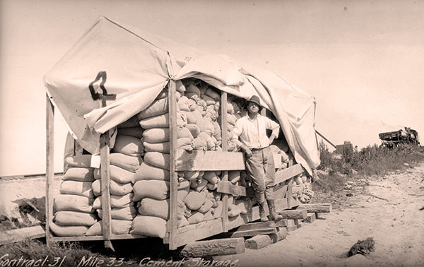
Cement store. Thirty-six kilogram bags of cement manufactured in Winnipeg were transported to the construction site for in-place casting of the aqueduct conduit sections.
Source: Winnipeg Water and Waste Department, GWWD #222.
Having a railway and the telephone system was fundamental to the implementation of the project. They were both installed by the GWWD before the major construction started and followed the route of the aqueduct. The railway was substantially completed in 1914 so that major construction could proceed in 1915. The telephone line was also built in 1914. The Chief Engineer noted that many sections were built twice, as the line often preceded the railway with the wire being carried on men’s backs and strung on trees until poles could be delivered by rail.
The railway system included nine sidings and five water tanks to supply the steam locomotives. The telephone became an invaluable communication tool for the GWWD staff as it enabled direct contact between the field operations and the head office in Winnipeg. After the completion of the project, the railway became a source of revenue for the GWWD by transporting materials to Winnipeg and servicing the settlements that grew up along the route.
Shoal Lake is connected to Lake of the Woods. The location on Shoal Lake where the aqueduct begins is on Indian Bay on the lake’s western edge. The longer dimension of Indian Bay is east-west and on the south side is an east-west oriented promontory of land. On its south side is Snowshoe Bay. The narrowest portion of the land between the two bays is about 840 metres and is close to the western shore of Shoal Lake. The Falcon River discharges into Indian Bay immediately south of where the water for the aqueduct is withdrawn. The Falcon River is the outlet of Falcon Lake some 10 kilometres to the west and also drains much of the muskeg area in between.
A dike and channel diverts the Falcon River water, which is coloured brown by the muskeg, into Snowshoe Bay and away from the aqueduct intake. The alternative would have been additional $1,000,000 expenditure (in 1913 dollars) to extend the intake further into Indian Bay. The intake is a dual-opening system with each one capable of accommodating 380,000,000 litres of water per day should the other side be out of service.
The dominant feature of the Winnipeg Aqueduct is the cast-in-place concrete conduit that conveys the water over the 118-kilometre distance from Indian Bay to a point 27 kilometres east of Winnipeg. The conduit consists of a parabolic arch resting on a concave slab that, when finished, was mounded over with earth fill to prevent frost penetration during winter. Mostly unreinforced, the conduit has some steel reinforcing at road crossings and undeveloped road allowances. When backfilled, it is generally above the natural ground level and would block the flow of streams or ditches in the local drainage pattern. The method used to lead the water across the right-ofway was a siphon that passes under the conduit. Siphons (technically, inverted siphons) were also used to cross the rivers—five of them—that intersected the route of the main conduit. In that case the conduits went under the river.
The portion of the aqueduct from approximately 27 kilometres east of Winnipeg to the McPhillips Reservoir, which is under pressure, was known as the Red River Siphon. The conduit in this section other than for the crossing of the Red River itself is made of precast concrete. An important and significant feature of that section is a pressure relief facility, a surge tank with an overflow system, located on the east bank of the Red River in St. Boniface—a unique structure for its day. To reach the McPhillips Street Reservoir in west Winnipeg, the conduit crosses underneath the Red. It crosses the river in the limestone bedrock some 24 metres below the banks and 6 metres below the river bottom. For that portion the conduit is a cast-iron pipe. Its profile consists of a vertical section built in a shaft on each river bank and a horizontal section built in a tunnel in the rock.
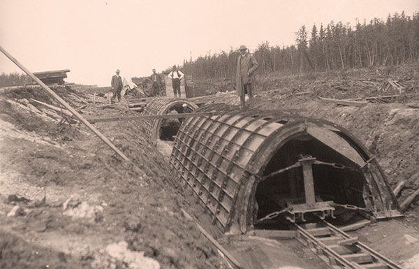
Alternating sections of the concrete conduit were cast in place. First, the invert or base slab was poured on the bottom of the excavated trench. Then, steel forms—such as those visible in the centre of this photograph—were erected to pour the arch section. Finally, the completed conduit was covered by soil. Reinforcing steel was not usually added to the concrete.
Source: Winnipeg Water and Waste Department, GWWD #195.
There is little doubt, given the challenges of the terrain, that the engineers responsible for the implementation of the Winnipeg Aqueduct were faced with uncertain situations and finite resources. The GWWD engineers and their Chief Engineer W. G. Chace had the benefit of the conceptual design routing in the Ruttan report that was the basis for the 1913 decision to proceed with the project, and the ongoing but intermittent advice of New York consulting engineer James H. Fuertes, but there were still challenges.
The parabolic arch which is the hallmark of the main conduit length, and which was featured in the GWWD’s logo, is notable because the concrete in the arch is always in compression so it did not require reinforcing steel. This feature saved a great deal of money and also lessened the chances of deterioration of the concrete due to corrosion of the steel. The engineers were also careful to keep the arch thickness to the optimum because they had estimated that a one-inch increase in conduit thickness would have cost an additional $400,000.
As part of the route selection mentioned above, the engineers had to factor in the depths of excavation along the route while striving for the most economical length and optimal gradient. They also had to design, test, and monitor the most efficient concrete mixtures based on local aggregate (gravel) sources and Portland cement supplies. They focussed on low permeability concrete to minimize conduit leakage while maintaining sufficient strength and durability.
To build the 136-kilometre conduit between Deacon and the intake, the engineers divided the overall job into five contracts, each of which took into consideration the terrain, site conditions, and complexity of the work. The call for tenders was advertised nationally and internationally and bidders were allowed to bid on one or all five contracts. Tenders were received in September 1914, a month after the beginning of the First World War, and awarded in October. The timing allowed successful bidders enough time to prepare for the start of construction on 15 May 1915.
As it happened, the low bidders on all five contracts were from Manitoba. The three easterly—and most difficult— contracts went to the Winnipeg Aqueduct Construction Company, a joint venture of Northern Construction and Carter-Halls-Aldinger (later Commonwealth Construction). Low bidders on the other two contracts were J. H. Tremblay and Thomas Kelly and Sons. Kelly was also later awarded the contracts for the surge tank, Red River crossing, and the section from the Red River to the McPhillips Reservoir. The Winnipeg Aqueduct Construction Company got the contract for the section from Deacon to the Red River.
Another aspect of the engineering department’s responsibilities arose from the decision, as a quality control measure, to supply materials to the contractors. The major components were aggregates (sand and stone) for the concrete and base fill, and Portland cement powder. Both required close coordination with the contractors. The gravel operation was based in pits developed by the GWWD in the vicinity of the project and involved excavating the material, screening it, and delivering it on time by railway to specific locations. The scheduling of the cement delivery was just as critical. Bags of cement had been manufactured by the Canada Cement Company at its Winnipeg plant. As part of the quality assurance program, the cement was monitored and tested on an hourly basis.
While the construction was under way, each contract was monitored by a division engineer and crew with responsibility for establishing the lines and grades for the contractor and also monitoring and inspecting the work. It is reported that grades were set at 30-foot intervals. If so, that would have involved at least 14,000 settings. An indication of how closely the work was inspected is a statement from the Chief Engineer that “These inspectors, in order that they may be present at all times on the work, live in tents at each point where work is in progress.”
Perhaps the most critical aspect of the on-site presence was to assess the foundation conditions—which could range from solid rock to quicksand—and determine the appropriate solution to unexpected and inadequate situations. Sometimes the solution was to drive wooden piles to support the conduit.
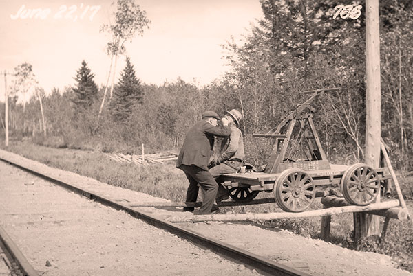
Dental surgery at siding 8, mile 82. Contractors were obliged to provide medical benefits to their workers, in return for which they could deduct 75 cents per month from wages owed the worker. These services were supposed to be meet the “satisfaction of the Chief Engineer.” One wonders to what extent the procedure shown in this photograph from June 1917 received supervisory approval.
Source: Winnipeg Water and Waste Department, GWWD #786.
Just as the engineers struggled to surmount problems as they arose, the contractors also had challenges arising from uncertain situations and limits on resources. It is one thing to draw lines on paper to represent the engineer’s design; it is another matter to turn them into a physical reality. The shear volumes of materials used during construction were impressive: 7,500,000 cubic yards of earth excavated and backfilled, 16,000 cubic yards of rock excavated, 455,000 cubic yards of concrete, 10,000 tons of reinforcing steel, and 575,000 barrels of Portland cement. The Chief Engineer noted that “throughout the entire construction approximately 1,000,000 cubic yards of sand and gravel were moved for concrete manufacture, for building up trench foundations where firm soil was at too low an elevation, and for backfill where native and local materials were scarce.” To put that volume in perspective, it would fill a Canadian football field to a depth of 300 feet (93 metres). All of that work was accomplished with steam power, horses, and manual labour.
Manual labour was a major contributor to the construction effort. At one point, 2,500 men worked on the project. Anticipating labour problems, the GWWD had laid down clearly defined rules. For example, contractors were required to pay their workers a wage in accordance with a Fair Wage Schedule stated in the tender documents, with employment preference given to local residents. (Later, when the war effort affected the availability of labour, that requirement was lifted.) Carpenters received a minimum of 35 cents per hour and were not required to work more than 10 hours per day. The number of hours to be worked per month was later clarified following a 1917 grievance to the GWWD Administration Board, wherein “260 hours work should constitute a month on any work under contracts.” Contractors were also required to provide board and shelter for their workers at a cost of $5 per week. This meant that a carpenter would have to work 14 hours to pay for his week’s food and lodging. The worker’s sleeping accommodation was required to provide at least 300 cubic feet (8 cubic metres) of space per occupant. The contract also required the employer to “employ the necessary duly qualified medical practitioners, furnish and provide all necessary medicines, surgical instruments, and hospital accommodation to the satisfaction of the Chief Engineer.” In exchange for providing medical service, the employer was allowed to deduct 75 cents per month from the employee’s wages.
Excavating and dewatering ground for the main conduit section, with conditions ranging from prairie to a nine-kilometre-long muskeg, was a major accomplishment, especially given the capabilities of the equipment available in those days. A requirement of the contract was that the bottom six inches of the excavation were to be excavated by hand so the foundation would be placed on undisturbed soil. It was also to be free of water. Neither condition was always met. Much of the bulk excavation was accomplished with steam-powered draglines. Unlike modern equipment, thse draglines did not have tracks but moved on rollers supported by timber rafts.
The concrete portions were formed and poured in two sections: the invert, or base, section and the arch on top of it. To allow for working room, the work proceeded in leapfrog fashion. The forms were made of steel and were reusable. The system was an efficient means of repetitive forming but still required over 70 setups for a kilometre or about 8,000 for the entire project.
While there was a great deal of physical labour in the excavation phase of the project, there was probably just as much involved in the mixing and placing of the concrete. Other than the actual mixing, which was powered by steam, the handling of materials was all by hand. The contractor’s light rail system was used for moving the mixed concrete alongside the trench for placing.
The surge tank presented a much different construction challenge than the other parts of the project. It involved a deep excavation, caissons dug to bedrock, precise placement of reinforcing steel, and special formwork ability. The formwork was for two concentric walls: one wall formed the tank and the other wall provided the catchment system to drain the overflow water to the river.
As noted earlier, the conduit for the river crossings is cast-iron pipe placed in a tunnel. While the work of tunnelling in rock under a river was no doubt unprecedented in Manitoba, there was another interesting construction aspect. The space around the pipe had to be completed filled with concrete to ensure there would be no movement. The final sealing was accomplished by a process know as tremie. Holes were drilled through the river bottom to the cavity above an initial encasement of the conduit and pipes were installed so that fluid concrete could be poured. When the concrete began to rise in an adjacent pipe, the cavity would be full.
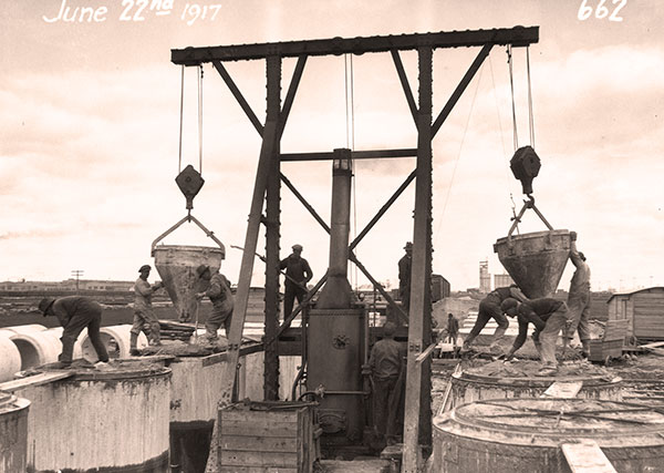
Pipe manufacturing in South Transcona, June 1917. One of the more controversial engineering decisions for the Aqueduct, endorsed by the consulting engineer, was to change the design of the section from Deacon to the McPhillips Reservoir. The original design called for a steel pipe. Concerns over electrolysis effects on steel from electric street railways, as well as price, caused the design to be changed to precast, steel-reinforced concrete pipe manufactured locally using local materials.
Source: Winnipeg Water and Waste Department, GWWD #662.
In the end, engineering and construction was an integrated process. And tension between engineers and contractors was inevitable. Nevertheless, a statement by one of the onsite engineers speaks to the collaboration that developed on the project. He wrote that in some of the more arduous site conditions “theory was of little use and reliance had to be placed on experience and sound judgement,” adding that the involvements of the contractor’s superintendent and the Chief Engineer in applying their experience and judgement was critical to getting the job done.
The GWWD began delivering water to the McPhillips Reservoir in December 1918—a remarkable accomplishment in just four construction seasons. However, because of a concern that there might be an adverse effect on the industrial boilers in the City due to a change from hard to soft water during the height of the heating season, the startup was delayed. Water began to flow into the McPhillips Reservoir on 29 March 1919 and the system was officially opened by the Prince of Wales on 9 September 1919.
The author acknowledges with much appreciation the contribution of the City of Winnipeg’s Water and Waste Department in providing a substantial portion of the information for this article. The minute books of the meetings of the Administration Board of the Greater Winnipeg Water District between 1913 and 1918 are stored at the Department’s Resource Centre at 199 Pacific Avenue, Winnipeg. Part of those records are 1,018 photographs taken at the time of the construction.
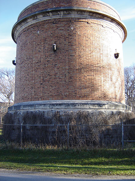
Surge tank. This cylindrical structure at the foot of Tache Avenue in St. Boniface provided a means whereby the pressure from 24 kilometres of water flowing through the Aqueduct at a significant velocity is relieved automatically if the rate of discharge of the downstream system is reduced. Without the tank, the conduit would burst.
Source: David Ennis
See also:
Historic Sites of Manitoba: St. Boniface Surge Tank (866 Tache Avenue, Winnipeg)
Page revised: 9 September 2022