by Gordon Goldsborough
Winnipeg, Manitoba
The process of making red-blue anaglyphs from historical stereoviews is not hard, so long as you have the right software and remember a few things. I use Adobe Photoshop CS2 (at writing, the latest version) but the same things can be done with most image processing software.
There are several web sites that describe the process, and I have boiled it down to the following four steps.
Jump to:
Step 1: Scan Stereoview | Step 2: Base Image | Step 3: Merge Left and Right | Step 4: Align Colors
Scan in color at a resolution of at least 300 dpi. (I prefer 600 dpi or higher so I have lots of pixels to play with.) You may wonder why one should scan a black-and-white photograph in color? Two reasons: 1) you preserve the original color of the mount, which may be interesting in itself, and 2) you will not have to convert the scanned image into color during later steps. You do not need a fancy scanner for this; I use a model that I bought for slightly over $100 at a local consumer electronics store.
Press them flat: Many early 20th-century stereoviews are curved, apparently on the thinking that this promotes the 3D effect when they are viewed in a stereoscope. Of course, this makes them harder to scan them on a flatbed scanner. I have found no recourse to pushing down on the scanner lid so it presses the stereoview flat. Otherwise, the center of the scanned image will be out-of-focus. You sometimes must press hard for thicker cards. Fortunately, the cards are quite resilient; I have damaged no cards during scanning - they always spring back into shape when the lid is opened.
Scan them straight: When placing the stereoview on the scanner platen, try to do it as perpendicular to the scanning direction as possible so the scanned image will be straight. Slight variation is not a big problem, and most software can straighten images that are not straight but I find that it is always better to start with as good a scan as possible, and rely as little as possible on software to fix problems.
Save the file as an RGB (red-green-blue) image in TIFF format. Do not use JPEG format at this stage, as it discards important data in the image and eventually causes it to degrade visibly.
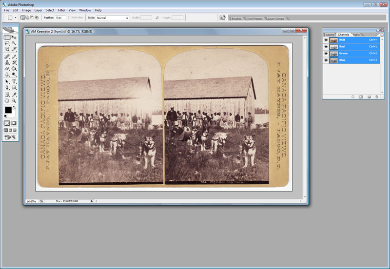
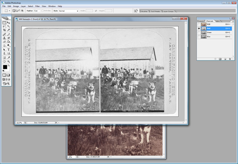
Here we have a stereoview from the Archives of Manitoba which I scanned from the original, loaded in Adobe Photoshop CS2. Notice that I scanned beyond the borders of the stereoview so I can preserve the whole look of the card, including its rounded corners. (Yes, this is probably something only a purist would notice or care about.)
This is a great stereoview taken by F. Jay Haynes (1853-1921) during his brief 1881 visit to Manitoba. It was probably taken at the Hudson’s Bay Company post at Barren’s River. Unfortunately, the left view has a white spot on its right side that obscures some detail in the background building. The right image is slightly darker than the left one. We can fix this easily using the Levels command in Photoshop.
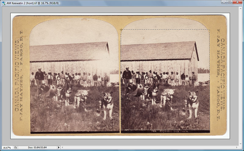
Select the image: Assuming the scanned image is straight, select a rectangular portion to use as the basis for your anaglyph. I am planning to create an anaglyph that is square whereas most stereoview images are taller than wide so I necessarily have to discard some part of it. In this example, I will crop the uppermost part of the image. It has no interesting detail anyway and, that way, we avoid the rounded top of the image.
It is essential to use the RIGHT image for this step, not the LEFT image. In a few rare cases, the paired images of the stereoview may have been reversed during the original construction, destroying the stereoscopic effect, so such photos can be fixed by reversing this step and using the left image as the base.
Copy this selection to the clipboard.
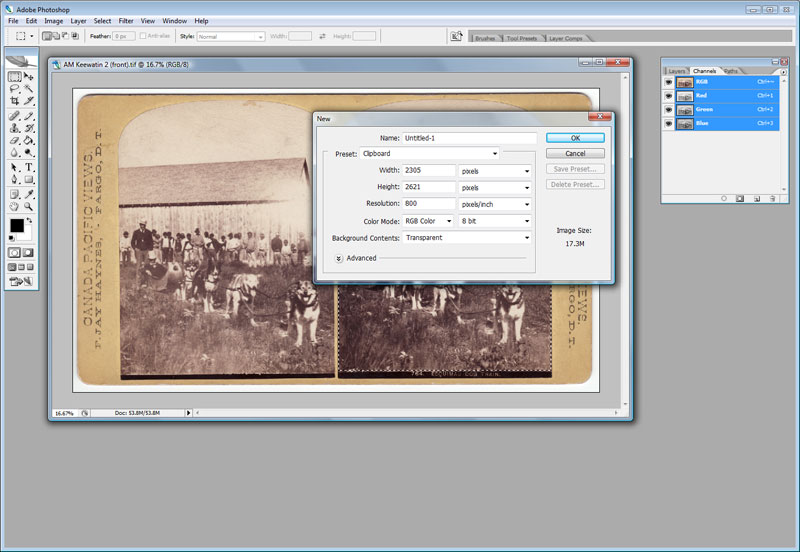
Now, I create a new, blank image having the same dimensions as my selection from the right image. The Color Mode of this image should be RGB Color.
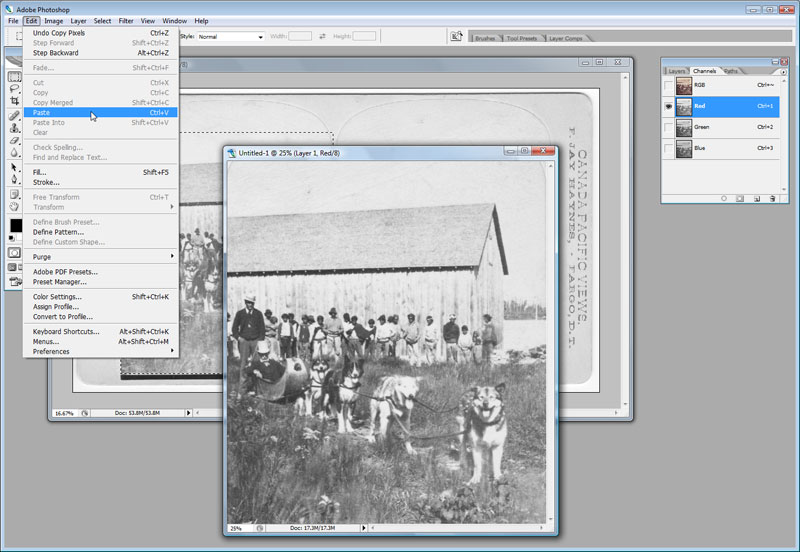
Paste the selection into it.
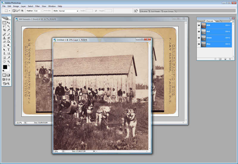
Here we have a new image based on the right image in the stereoview. Notice the Channels window in the upper-right corner of the Photoshop window? It shows me that the image is RGB and all three color layers (red, green, blue) are presently being shown.
Go back to the original stereoview scan. Move the selection marquee from the right image to the left one, being as careful as possible to cover the same part of the image. (In other words, if you did not select the entire right image, then you should make sure to select about the same proportion of the left image.) When you have made a selection of the left image, select its red channel in the Channel window.
The image appears to lose its color at this step, turning into a grayscale image. Do not worry; this is merely because we are viewing just one of its color channels. It is essential to make sure that you are viewing ONLY the red channel so the next step will work correctly. In other words, there should be an eye icon to the left of only the red channel, not the green, blue, or RGB channels.
I copy the red channel of the left image to the clipboard (Edit-Copy command), then I go back to my new image based on the right image. I make sure that only its red channel is visible - again, the eye icon is visible to the left of only the red channel in the Channels window. Then I paste the left image from the clipboard into the red channel of the right image (Edit-Paste command) shown above.
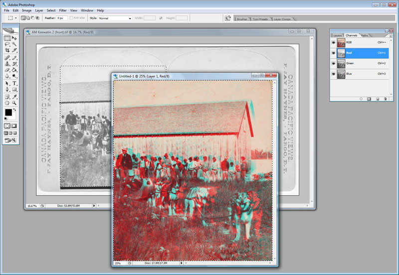
At first, the only thing that seems to happen is that our new image is replaced by the one from the left image. But this is because we are still viewing the red channel only. Turn on all color channels (by click on the RGB channel) and, voila, the first version of our anaglyph appears as below.
This is the most important step, so be sure not to skip it!
You may be inclined to stop at this point. You can look at this image with 3D glasses and it should look somewhat three-dimensional, but we can do better. This raw anaglyph probably has lots of blurriness, with “ghosts” around many of the objects in it. We must align the layers to maximize the three dimensionality.
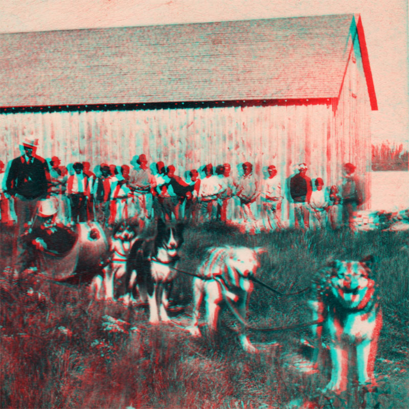
Select the foreground. Pick an object in the anaglyph that you want to occupy the foreground of the three-dimensional image. In the above example, I chose the lead dog in the pack. All other dogs, as well as the people and the building should appear behind the lead dog.
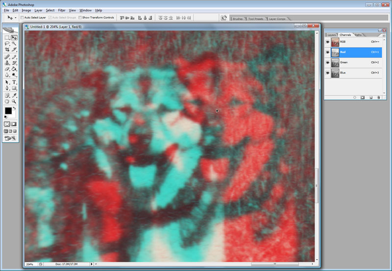
Zoom in on this foregound object. To fine-tune the positioning, I zoom in on the lead dog, then make sure that I am viewing all color channels but the red channel is the active one. (The red channel is highlighted in the Channels window.)
Here I am looking at the nose of the lead dog. My goal is to move the alignment of the red channel so the details of the red and green align perfectly, so neither color is visible. When I view the image with my 3D glasses, the nose appears at the surface of the image and all other parts are behind it.
Note that it is possible to select another object behind the dog’s nose to be the foreground, in which case the lead dog will seem to leap out of the image, in front of the page. I know this sounds cool but, in most cases, it actually looks odd. But suit yourself.
In my final version, I found that I got better results for the image as a whole if I selected the third dog from the front as the foreground. This causes the lead dog is be somewhat colored.
After a bit of tidying up, cropping the image, resizing it to the desired final dimensions (in my case, 800 pixels by 800 pixels, at a resolution of 72 dpi) and adjustment of levels to improve contrast, we are done. Here is my version of the anaglyph:
Source: Archives of Manitoba, Keewatin 2, N13748.
“764. Esquimau Dog Train” Dog team & cariole, stereoview by F. Jay Haynes.
Page revised: 1 March 2024